DXC card

.jpg)
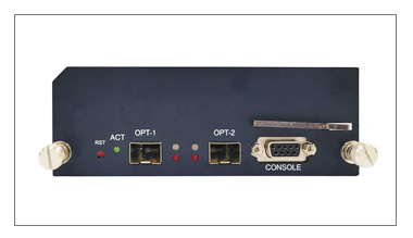
The DXC board
The DXC board is used to control the multiplexer.

Figure 1.2. The main DXC board.
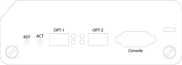
The DXC board has a reset button, an LED activity indicator, two sockets for SFP modules with two status indicators each and a DB-9 console port (RS-232) for initial settings of the multiplexer.
The DXC board has two connectors for the operation of STM-64 or STM-16 SFP modules. Both connectors have an operation indicator (WK) and a fault indicator (FLT) for visual indication of the module status.
RESET button and LED activity indicator (ACT)

Figure. 1.3. Interfaces SDH.
In ON-9864, there are two connectors on the DXC board for STM-64 or STM-16 SFP modules. Each connector has an operating status indicator (upper) and a fault indicator (lower) for visual indication of the module status.
If 2 DXC cards are installed in the multiplexer, then their optical ports in The web interface is numbered as follows: M1 DXC OPT-1 – MX, Port-1.
M1 DXC OPT-2 – MX, Port-2.
M2 DXC OPT-1 – MX, Port-3.
M2 DXC OPT-2 – MX, Port-4.
Console port
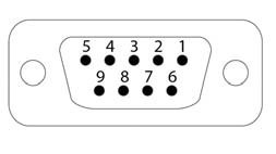
The console port provides the user with a command line interface (CLI) for the initial configuration of the multiplexer and its diagnostics. It has a DB-9 connector, socket. Detailed information is given in appendix B. The connector diagram is shown below.

Figure 1.4. Console port (DB-9, socket).
The assignment of the console port contacts is given in Table 3.1.
| Pin numbe | Function |
| 1 | NC |
| 2 | Tx |
| 3 | Rx |
| 4 | NC |
| 5 | GND |
| 6 | NC |
| 7 | NC |
| 8 | NC |